The root of simulation – a 3D CAD model
It was not really that long ago that parts and tools were designed by using a drawing board and a T square. Of course, CAD came along and changed the way engineers drew and designed. Initially, 2D CAD simply made the drawing board electronic. While this in itself was a huge step forward, it was soon trumped by 3D parametric modelling.
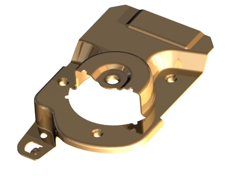
At the root of simulation (and almost any FEA virtual testing environment) is a 3D CAD model. This means there is a full mathematical X,Y,Z representation of a part or die face in a common CAD format such as IGES. Furthermore, surfacing is required. Whilst some earlier 3D CAD programs drew in 3D wire frame, the wires needed to be connected and surfaced for use as simulation “surfaces.”
More and more CAD programs use SOLIDS or a combination of wires, surfaces and solids to mathematically represent the designer’s intent. Whatever the method, the result can almost always be outputted as IGES surfaces in 3D. It is a standard “Save as” option of almost every CAD package on the market. So to keep it simple, 3D data is the standard and StampingSimulation.com always requires 3D CAD data to perform simulation work.
While it is not unforeseen that some companies may not have access to the 3D CAD model (for example, an OEM has only issued part prints for quotation), it is always attainable from the designer and should be sought after as standard issue. In the few cases where a simulation job could be dealing with legacy tooling or part designs, there will be the option of using 3D digital laser scanning, to capture the tooling surfaces or the part shape with a high degree of accuracy. Such equipment is becoming more and more common and affordable.
The bottom line is this: 3D data is a fundamental requirement for all forming simulation jobs.
Contact Stamping Simulations with any questions you may have about 3D CAD model.