What Is Tooling Offset and How Is It Used?
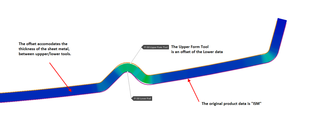
A tooling offset is required in all physical sheet metal tools. That is, there must be a physical gap between the male and female tooling, to accommodate the sheet metal thickness.
It is common, particularly in the early years of 3D CAD modelling to design the sheet metal product as a single sided part, with zero theoretical thickness.
That is, the designer does not physically add the thickness of the sheet metal to the 3D model. Adding the physical thickness to a 3D math model is sometimes difficult — and maybe even impossible — for very complex sheet metal parts with complicated radius transitions and junctions. Although 3D CAD software has improved enormously, not every 3D surface model will successfully “thicken” (aka offset) to form a solid 3D part model with thickness.
Therefore, an offset (ie: the allowance for sheet metal thickness) may be applied later by either the tool designer or in simulation or by a CNC operator during tooling manufacture, having only the “master” surface data as the reference shape. Often the pain of physically creating the “other side of metal” in the 3D data is not required, although simple sheet metal parts may thicken or offset without much effort.
In simulation, it is not required to have the tooling offset in the initial 3D data that is imported. Almost all sheet metal forming simulation software will create an offset automatically for FEA purposes, without any limitations. This is because a MESH based offset is created in the simulation environment, and the imported CAD data is not the basis of the offset. Rather, the CAD surfaces are first meshed and then the offset is applied to the FEA mesh. There is no possibility to export the new offset as a usable CAD surface or solid.
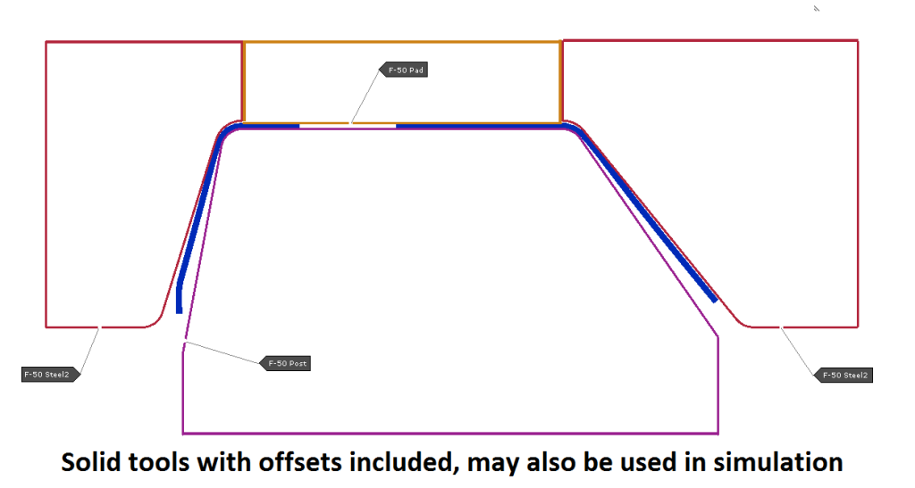
It is also worthy to note that tooling and/or part models that already contain thickness (or offsets) can be imported to simulation and meshed with the physical offset already in place, without further offsetting.
To clearly define and communicate the “master” surface and which direction an offset must be applied, often the terms Inside Sheet Metal (ISM) and Outside Sheet Metal (OSM) are used.
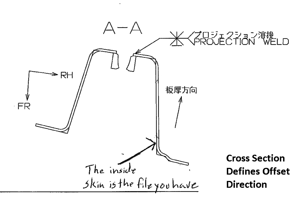
However, these terms are not 100% definitive and, for some sheet metal parts, these terms are still ambiguous! Therefore, a cross section diagram may also be provided to clearly define the required offset direction such that there is no doubt to anyone interpreting the 3D data. The “master” surface is sometimes referred to as a “skin”.
To make things more confused, the industry does not conform to any strict terminology standard in this regard. While the terms ISM and OSM are commonly used in the western world, time spent with different OEMs will yield some different terminology!
For example, Toyota Motor Corporation historically always defines the “punch” surface of the sheet metal as master (“punch”, as in the male side of the tooling that would produce said part, which in itself could be ambiguous outside of Toyota!!)
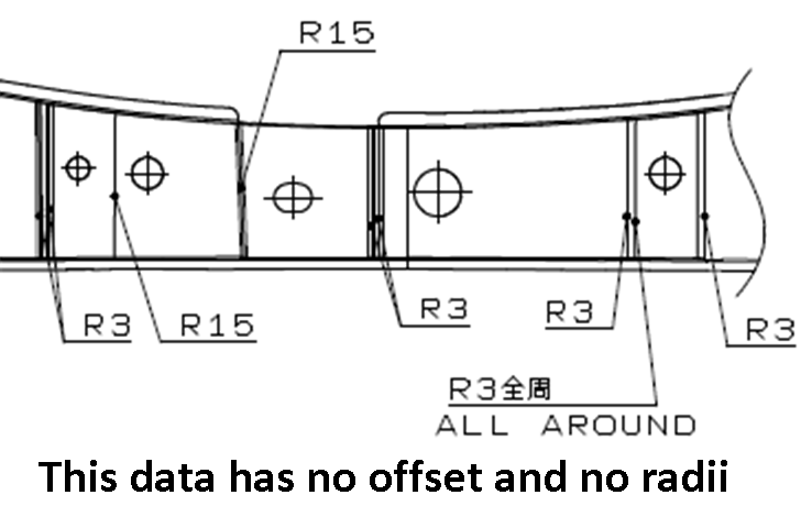
In Japanese, the initial CAD models and drawings for sheet metal parts are referred to as the “punch-ii-e” which literally means the “drawing of the punch side”, and historically rarely contain the product radii, but just define the faces of the product. A “radius instruction sheet” is often provided in addition to the product drawing in the case of Toyota.
At Stamping Simulation, our industry experience and training gives us all the expertise we need to work on any project that includes tooling offsets you may have. If you’d like to talk to our team about your current or upcoming projects, get in touch. We look forward to working with you!