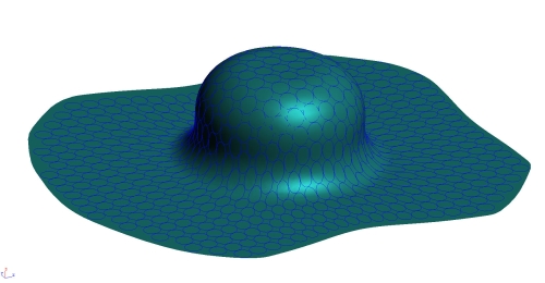
Virtual Circle Grid Plots
It is common practice for a toolmaker to scribe or etch a grid of circles onto a blank during the tooling development stage. Then, the etched blank is put in the nearly finished tool (or proto-tool) and the sheet metal is formed. As the forming takes place, each circle (which was perfectly round with a known diameter, when it was etched onto the blank) stretches according to how much strain is experienced at that point, as determined by the shape of the part and properties of the blank material.
Often a toolmaker will study the deformed circle pattern to gain an understanding of how the material is behaving, in order to assist with solving a forming problem such as wrinkling or splitting. With this information, an informed judgement can be made as to what changes to the tooling are required to solve the problem. This is also the basis of a forming limit diagram. At each of these points, the strain (or amount of stretch) can be measured in two directions, commonly known as the major and minor axis. Then each value is plotted on the FLD to determine whether the amount of straining is beyond the materials limits or not.

So this means the FLD basically replaces a circle grid plot, right? Not entirely. While the FLD is an excellent tool to show strains all over the part, sometimes it is difficult to see which point in the part corresponds to which point on the FLD. The circle grid plot allows the point in question to be directly related to the point on the part, since the circle is etched on the part itself.
Many toolmakers may also prefer to study a circle grid plot rather than an FLD diagram but ideally, both a circle grid plot and an FLD should be studied together to get the best understanding of how material is behaving during the forming process.
Furthermore, a virtual circle grid plot can be compared to an actual circle grid plot to determine the accuracy of the forming simulation or to simply confirm that the forming simulation is accurate. In fact, this is the basic method for verifying that forming simulation does in fact yield realistic results. Thankfully, it has been done to death already and proven that forming simulation does predict accurate results, provided the simulation is performed correctly and realistic parameters are used.
However, for your own satisfaction you may wish to confirm a virtual circle grid plot against an actual circle grid experiment in your own tool room. Of course, upon request we can provide a virtual circle grid plot with the results of any forming simulation we perform.
