The capabilities of Simulation
We would like to explore the capabilities of forming simulation, as well as provide some descriptions of how the technology works. So here is a quick summary of a few typical applications of press forming simulation technology. Being aware that press forming simulation is actually a specific application of the Finite Element Method (FEM also known as FEA) may assist your understanding.
Material yield (utilization) calculations and blank shape estimates.
Using a 3D CAD model of the final part, the data is meshed automatically and then “unrolled” or developed to a flat blank shape. From here, blank nesting and rectangular, trapezoid or any other shape fitting can be applied. The final data produced is a 2D CAD line that can then be used to calculate material utilization across any blank nesting or shape configurations.
Tip angles (or part tipping) and undercut checks.
Using the 3D CAD of the final part shape, the data is automatically tipped into the most suitable pressing angle with the intent to ensure that no elements in the mesh “undercut” the vertical motion of a press machine. This step provides a very quick indication of the possibility of forming the desired part shape in one process or whether there is a need to do it in two or three or more processes. If there are undercutting areas, they are highlighted and decision can be made as to whether the part shape can be changed (to avoid the undercutting) or whether an additional forming process is needed. This step sets the press tip angles and positions the 3D CAD model into the pressing coordinate system, ready for further die face designing.
Forming simulation (or drawing simulation).
Of course, this is the main purpose of this Web site, but the result is much more than just a simulation. At first, die face data has to be created. Using the final part shape that has been tipped into the pressing direction, die face surfaces are created. For example, in a simple crash form, the boundaries of the part simply need to be extended, but in a draw process, addendum and binder surfaces need to be created. With this, the earlier developed blank shape (square, pre-trimmed or otherwise) is used with the newly created die face surfaces to run the simulation.
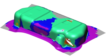
Splitting, thinning and wrinkling checks.
It goes without saying that the primary purpose of the forming simulation step is to check how the material behaves prior to machining of any tool steel.
The results produced in the forming simulation step illustrate very clearly the calculated areas of material yielding (splitting), amounts of necking (thinning or changes in thickness) and areas of material compression (wrinkles and folds). The Forming Limit Diagram (FLD) is key to analyzing this data as it plots each element’s strain (in major and minor axis) on a graph and compares it to the material’s limits to determine if any of these defects will be present. With this information in hand, countermeasures and adjustments are made to the die face design and then the forming simulation is re-run, until each defect is removed or an acceptable result is achieved.
Die face data export.
After all the problems have been ironed out of the draw process and an acceptable “draw panel” has been produced in the virtual environment, the die face data that was used in the simulation can be exported as CAD (IGES, STL or any other format) for use when designing a complete tool and creating NC cutter paths. Basically, the die face data can be used in any other CAD/CAM package for use in an actual tool build.
Blank shape development.
There are many cases where it is not possible to simply blank the material to the shape estimated in the first step (blank shape estimate), form it and end up with a perfect result. If the part needs to be drawn then wiped down, for example, then some trimming occurs after drawing and needs to be developed so that after the wipe-down, the trim length is correct. With the simulation software, this can all be done in a virtual environment. After the draw simulation step is complete, the “virtual draw panel” can be virtually “laser trimmed”, then wiped or flanged down. The virtual laser trim shape can then be adjusted until the final trim line is developed to the correct shape. This means when the time comes to develop an actual trim die, a very accurate starting point is available, which rarely needs further adjustment, meaning the time and cost to build a real trim die, is drastically reduced.
Multiple-stage forming.
If a part cannot be formed in a single stage then each subsequent stage can be simulated and checked too. It is simply a matter of taking the result from each previous stage and feeding it into the next. The previous stage results may include a draw, a trim, a hole pierce or any other operation, each of which gets carried over into the next stage’s simulation.
Pierce hole roundness checks.
You may have realized already that it is possible to simulate a forming process with a hole pierced in a blank. This gives an accurate simulation demonstrating whether a hole can be safely pierced in a blank stage, then drawn, without losing its roundness or desired position (usually determined by the quality specification of the final part). Conversely, such a simulation may show that an unimportant hole will go “egg shaped” after forming, but if acceptable, it can remain as a hole pierced in the blank, as opposed to piercing it last, when maybe a cam unit or something else would be required.
Springback check.
A springback check can be performed after any stage, for example, after the first draw stage or after the final stage. The end result is not just a number on paper of the amount of springback, but a full 3D CAD model of the part in the sprung back state (that can be exported in any CAD format). This means it is very easy to use this data to counteract the springback or decide if the amount of springback is acceptable or not.