The basic steps of die face design
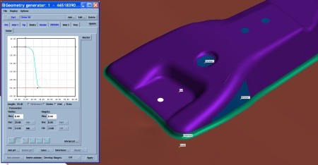
When using a tool like AutoForm to design die faces, with the intent of simulating the design for verification, there is a basic path or set of steps that are used to end up with a die face design. We will nowbriefly out line such steps.
When using a tool like AutoForm to design die faces, with the intent of simulating the design for verification, there is a basic path or set of steps that are used to end up with a die face design. We will nowbriefly out line such steps.
As we have mentioned in many of our blogs, a complete CAD model is needed that has radii. The first and foremost step is always a blank shape estimate, but this is not really part of a die face design, rather it is an indication of material usage for budgeting purposes and later use in simulation. So actually, the first step in a die face design is to inspect the geometry of the part and perform an undercut check.
If it is possible to form all of the part’s shape in a single form stage (be it crash form or a draw) then an attempt is always made to do so. This is done by tipping the part’s geometry into the most favourable pressing angle, then extending and adding additional geometry (where needed) to ensure that the blank will be “captured” by the tooling surfaces and formed correctly.

If a 100% developed blank shape looks like being a possible solution, then this basic die face design is simulated with the earlier blank shape estimate. Note that at this stage, the dieface design is basically just the part’s shape with no allowances for springback or hard to form areas.
Of course, if the result of this simulation is successful and accepted by the final part’s quality standard, then the die face design is complete and a tool can be machined from the data used in the simulation. Naturally, a lot of times a single stage form with a 100% developed blank outline produces large wrinkles or folds and splitting and the die face design process does not stop here.
From the simulation of the single stage form, forming limit diagrams, thinning plots and circle grid plots are analysed carefully, to give a good understanding of how the material is behaving, in what directions it is being stretch and where the problem areas are. From this, it can be decided what sort of pre-form is required to ensure problem areas are ironed out in the final form stage.
From this point, the die face design starts to differ from the final part’s geometry. Pre-draw geometry must be created that carefully considers the problems encountered in the single stage form simulation. For example, a deep drawn cup shape may need an over drawn bowl shape to start with. This is where the software does not magically come up with a die face design and the skill and experience of the die face designer is required to produce suitable geometry.
Of course, the huge advantage is that many different variations can be tried and tested in the virtual environment to get the pre-draw shape just right, before a tool is manufactured. Furthermore, if either of the form stages require draw beads to help control material flow (to prevent problems like wrinkling) then draw beads can be simulated too.
Again, the software is not magical and placement, length, shape and size of draw beads needs to be considered by the die face designer. The determination of such parameters for draw beads is again based on the results seen in the single stage form OR the results seen in a draw stage WITHOUT draw beads. The great thing about using forming simulation is that experiments with different types, lengths and placements of draw beads can be performed for little expense and the best result can be chosen for use in an actual tool build.
Once all die faces of each forming stage (including draw beads, if required) have been designed and tried in the virtual environment, the final virtual part can be subjected to a springback check. If the amount of springback is un-acceptable in the final part, then a further die face design revision can be made in any of the form stages, to countermeasure the predicted springback.
Finally, once satisfaction with all the simulation results is achieved, all die faces that were used in the simulation are converted to CAD and exported for use in an actual tool build.
