From Product Design to Simulation: How to Start Your Manufacturing Project
Contents
Designing a new product is very exciting, be it for an existing company or for a startup. In order to guarantee the success of your project, one must take the right initial steps and lay the right foundation. Once you have designed your product, you have to figure out the materials and process for its manufacturing. In this article, we discuss how to use our simulation services to save time and money overall for your sheet metal manufacturing project.
Step 1 – Provide a 3D model of your product design
The first step to any manufacturing project is to create a 3D CAD model of the desired product. Although the initial product shape may start out as a simple sketch or 2D drawing, the end result must be a computer-generated 3D model, to enable the use of advanced computer simulation technology. If a 3D model is not available OR the product was produced a long time before CAD, then a sample part is required to create a 3D model. StampingSimulation can provide 3D modeling services whenever required.
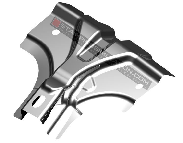
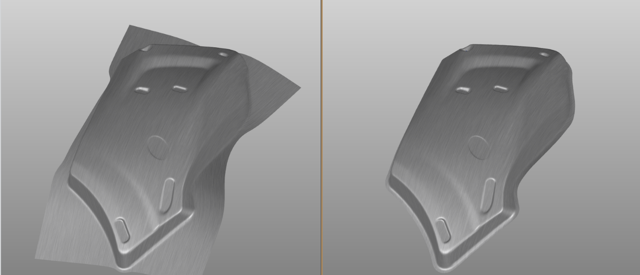
A typical sheet metal product design
Step 2 – Determine a Forming Process
Starting with just the product shape of your sheet metal part, the next step is to estimate and design an initial metal forming process, eg: Draw, trim, form, pierce holes. The initial design is just the first idea to be simulated and is often not the best nor the final result!
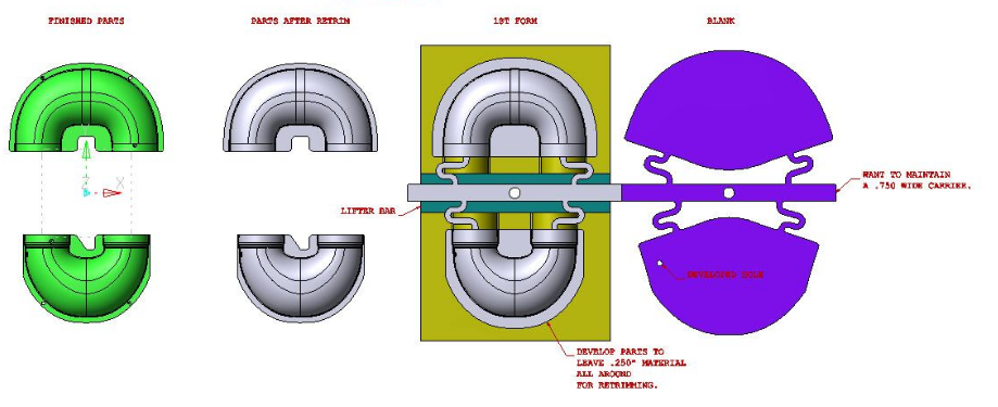
A possible forming process for initial simulations
Step 3 – Engineered with Simulation
In fact, the whole point is to try as many ideas as possible, to determine the best and most optimized process. Only the advanced tools in AutoForm make the task of revising and simulating multiple times fast and efficient. That’s why when you ask StampingSimulation to design and simulate a process for your sheet metal product, we allow a minimum of five iterations to design/simulate a solution. If the solution is “found” on the first try, there’s a good chance it’s not optimal and further simulations will “find” opportunities to cut cost and save time.
Typically, StampingSimulation will show you initial results in <36 hours, and present possible optimized solutions within 3~5 days, often less.
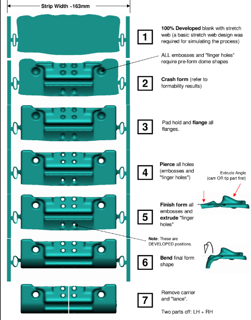
The final process after multiple revisions and iterations in simulation
Step 4 – Results delivered
Only once we determine the optimal and successful process in simulation, is the tooling data generated in CAD. The tools in AutoForm are so powerful, it is inefficient to use CAD to generate tooling shapes until the very final step. The simulated tooling shapes are turned into clean CAD models and the solid tooling data and developed blank shapes (or cutting curves) are provided to you for each forming step, giving your tool designer the fundamental building blocks for a successful outcome at first tryout.
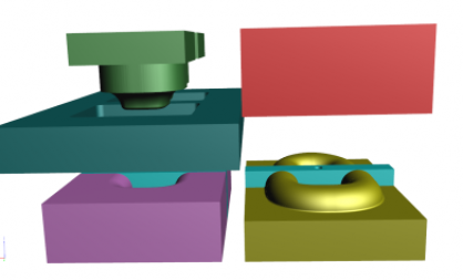
A set of solid tooling data, for use in a detailed tool design.
Step 5 – Validation
StampingSimulation always provides one extra simulation, beyond any included simulations–Final Validation. Once your tool design is complete, and just before it is ready to be manufactured or tooled, StampingSimulation will provide one further simulation to ensure your final tool design will deliver the expected result. The most common error is for seemingly small changes to be made outside of simulation, that change the end result. If the final tool design is checked in simulation, there can be no unexpected surprises! It is also essential to use lab-tested material data during this step.
The final tool design is checked again in simulation
Learn More
Interested in learning more about what is possible with advanced forming simulation software? Take a look at a few of our case studies and see what’s we’ve accomplished for our clients.