Process Planning for Beginners From the Drawing Board to Production
Contents
Process planning is an essential part of any manufacturing project. That said, it involves a series of different elements and many organizations tend to miss small, yet vital details. This article works as an introductory guide to process planning and its benefits. Also, we discuss how to set up a successful planning stage and highlight how a professional company can help develop accurate plans for all stages of production.
Previous Means of Process Planning
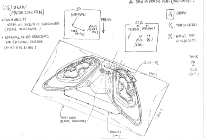
In the beginning, process planning was done by hand, whereby engineers would sketch on paper the proposed process that would be the basis for a tool design. This example shows three stages:
1. Draw
2. Trim & Pierce
3. Flange, Trim, & Separate
The process plan is mostly visual and uses a 2D CAD print as the basis for the hand sketches. In the DRAW stage, we can see the blank size is estimated, and also the blank draw in (suck line) is sketched. The author of this sketch is unsure about the need for a custom blank shape (see notes: “MAJOR CONCERN”) and also worries about the die structure.
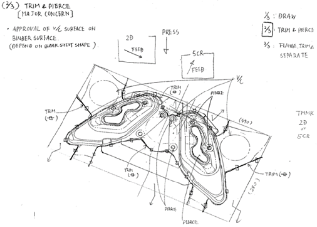
The feed direction is noted, as well as surfaces of the drawn sheet that will be used for vacuum cups, which would indicate this tool will be placed in a mechanical (or robotic) transfer line. A concern about placing the vacuum cups (v/c) on the binder surface is noted. Scrap cutting, as well as trimming profiles, are also sketched in the TRIM & PIERCE stage plan.
In the final stage (FLANGE, TRIM & SEPARATE) we can see the planner is concerned about unloading the parts, on either of the proposed press lines (2D or 5CR).
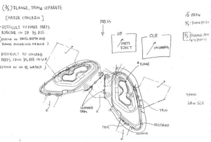
Overall, this process plan is a rough draft and barely adequate to confirm whether this part can be made successfully or efficiently. At best, the dimensions and sketched profiles are a guess and cannot be used as design data for tooling manufacture. Naturally, this rough process idea would be developed further with the use of CAD, perhaps 2D at the time of the sketches.
Modern Process Planning
In the year 2018, we can do a lot better using advanced simulation technology such as AutoForm. Although the hand sketches are useful as a starting point, the time and effort required to generate them would be somewhat wasteful in 2018. Using AutoForm, we can generate process plans using the 3D product model.
By starting with the 3D product model and planning in 3D, we initialize very powerful simulation tools that will not only allow the process engineer to propose a process but to simulate every step of the metal forming method to determine if the proposed process will succeed…or not.
Furthermore, the guesswork around blank size, draw line suck, trim profiles, and surfaces for vacuum cups is eliminated. By planning the process AND simulating the entire process in AutoForm, the unknown parameters are accurately calculated.
The most successful method for process planning in 2018 and beyond, is by using powerful 3D tools and simulation combined to replace 2D sketches (even those in CAD), which are too simplistic to capture and calculate the complex nature of a complete sheet metal forming manufacturing process.