Insider Tips: 5 Key Elements of Sheet Metal Forming Simulations
Contents
There are many different factors that will influence the success of a simulation, and not all of them are necessarily up to the supplier. There are many different elements that sheet metal simulators need to take into account in order to set up the right expectations. This article discusses the different factors and parameters that may affect sheet metal simulations and what simulation engineers can do to counter or prevent them from influencing their results.
1. Incremental vs One Step simulations – know the difference
2. Simulate every stage – every process step of the tooling
3. Know Thy Steel – simulations must be validated with lab tested material
4. FEA settings – fast vs accurate
5. Pressures, forces, and lubrication – simulation inputs must match reality
Let us expand on each of these in more detail:
1. Incremental vs One Step simulations
“One Step” simulations are inexpensive, fast, and require little input other than the final product shape. “One Step” simulations, in some cases, are a giveaway result with online software available for little or no cost. See EasyBlank Cloud Service here. Full incremental simulations, in comparison, require every detail of the tool design to be included such as blank shape, material data, tool geometry of every stage, pad/binder pressures, etc. Needless to say, only incremental simulations yield highly reliable results when input data is realistic and matches what will be built in reality. StampingSimulation uses AutoForm incremental for all simulations.
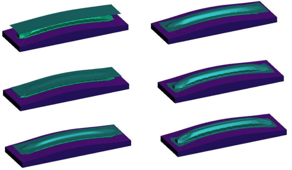
Only incremental simulations can show every increment of the sheet forming at any stage
2. Simulate every stage of the tooling
How many tool stages will be built? For some simulation software, simulating EVERY tool stage is a daunting task and is sometimes avoided, due to software limitations and inefficiencies. In AutoForm, it is routine and efficient to include every process stage in the simulation, and in fact, run the simulation many times over to optimize the number of tooling stages. Only by simulating every tooling stage can simulation match reality. If you plan to build it, simulate it.
3. Know Thy Steel
This has been said many times over. No simulation is valid without lab-tested material data. Knowing the steel you are testing is another element of simulation. Anything other “library material” is a rough guess and does not provide reliable results.
Thyssenkrupp Steel provides lab services to StampingSimulation
4. FEA settings
In this day and age of powerful multi-core desktop computing, there is almost no need to compromise on accuracy, for the speed of computation. Perhaps the largest of large sheet metal parts (think body side outer panels) may benefit from “reduced” mesh settings OR “draw element” settings to provide an initial look at the formability of a large and complex part. For all other medium and small sheet metal parts, never compromise mesh settings for accuracy. Using AutoForm “final validation” settings, StampingSimulation always reports the most reliable results using the most accurate FEA mesh settings.
5. Pressures, forces, and lubrication
While it is true the software will calculate and report the ideal pad/binder forces for each and every tooling block, the forces “found” in the simulation must be replicated in reality. For this reason, initial simulations should allow the software to calculate the optimal force, but subsequent simulations (ie: final validation) should have the final designed force as inputs to the simulation. For example, if the optimal binder force is calculated to be 300 ton, but the press machine cushion can only provide 250 tons with a linear increase, then the 250-ton linear increasing force curve should be used in a simulation.
If you have more questions or need expert help contact us, we have state of the art technology and production to match your design perfectly at a cost that you can afford.