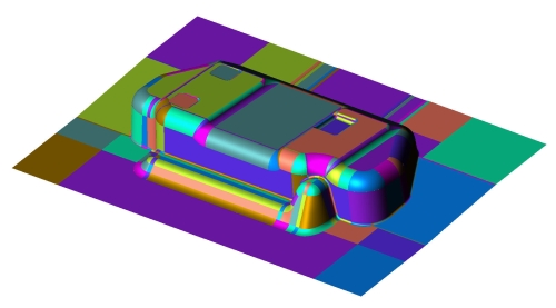
How does the quality of my CAD model affect results?
The most important aspect of any forming simulation is the CAD model and it all starts with the blank shape estimate. In order to perform the blank shape estimate, a complete CAD model of the final part shape is required. By complete we mean complete with surfaces and fillets (or rads).
In the earlier days of CAD design, wireframe data was used. In fact, some large companies still use wireframe data today. This is basically just two points joined by a line and the end result is a “spider web” or wire frame of the final part shape. Of course, this type of data contains no surfaces or fillets or radii. Therefore in this form, the data cannot be used in a simulation. In fact, in this form the data could not be used to generate NC cutter paths either. If you or your customer is still using wireframe data to design press metal products, then a fair amount of work is required before it can be used in a simulation.
From the wire frame data, surfaces must be added. Depending on the size and complexity of the model, this can be a very tedious and time-consuming task. This can be done in a CAD package that is capable of creating surfaces such as CATIA, Rhinoceros or Mastercam. At this point, the result is usually a “square” model, i.e.: a model without fillets or radii. Since it now contains surface data, it is possible to perform a blank shape estimate; however, the result is obviously less accurate than that from a model with complete fillets. So the next step is to add fillets at each of the “square” edges. This also can be a very tedious and time consuming task, again dependent on the complexity of the part design.

At this point, we are still dealing with surfaces, and anyone who has had experience with filleting surfaces will understand the difficulties involved with manually filleting surface data. It usually involves extending, trimming, sweeping, blending and cleaning up surfaces one by one until the final smooth filleted model is produced. Because of this long, tedious procedure, models built from wire-frame data usually contains many errors such as overlapping surfaces, mismatched surface edges, untrimmed surfaces, missing entities etc. Luckily, if you are still using wire-frame data, StampingSimulation.com can provide all the above as a service, if requested. But even more fortunately, many of you use solid modelling CAD packages such as Solidworks, Solidedge, CATIA, Inventor, Unigraphics etc. This means your data is basically fully surfaced from the second you start designing, and filleting is as simple as point and click, with all the blending and fillet intersections taken care of by the solid modelling software. Also, thickness is added at the click of a button, resulting in upper and lower tool surfaces.
So is it fair to say that a solid modelling package produces top-notch CAD models? Yes and no! Yes, while working within the software that created it, the data is of course top-notch. But when it is exported to IGS, STEP or some other common format, some translation problems may result. Forming simulation software naturally reads the more common formats such as IGES, so therefore it is usually necessary to work within a different format than that in which the original model was created. When you upload a CAD file to StampingSimulation.com, we translate it to IGES before using it in the forming simulation software. This means any problems we encounter in translation from the original format can be dealt with at our end instead of hassling you, the customer, for different formats.
So be assured, if you have a solid model of your part and it is complete with fillets, then there will be no hassles when you upload it to us.
