The Future of Sheet Metal Forming Simulation Software
Contents
It is remarkable to look back and see how far sheet metal forming simulation software has developed. Reflecting from personal experiences, I started with LSDYNA based software around the year 2000, which required many, many hours of meshing, mesh repair, and manual inputs of tooling travel curves (amongst many other tedious inputs) before a simulation could be sent for “Solving”.
Furthermore, the earliest sheet metal forming simulation software was basically three different software packages linked together and not at all streamlined for ease of use. We used to deal with “preprocessing” (ie: meshing of tool geometries, and all other inputs), then “solving” (the actual number crunching by the CPU), and finally “postprocessing” (viewing the result).
The Development of AutoForm Software
In the early 2000s, I came across AutoForm software. This software had an entirely different approach and method for accurately solving sheet metal forming simulation problems. The most notable of which was the complete automation of the tool geometry meshing phase — an incredibly robust mesh/solver combination that requires basically no further “adjustments” from the user.
The ideas of “pre”, “solver”, and “post” were also turned on their heads with a single common GUI being the AutoForm trademark and a market leading advancement. Automated trim development and iterative spring back compensation were also amazing and significant software developments by AutoForm.
There are numerous other functions that I could continue to list. It leaves me wondering, what will sheet metal forming simulation software allow us to do next?
Sneak Peeks at New Sheet Metal Forming Simulation Software
There are already some hints of what the next major AutoForm advancement may be. Although I am only speculating based on my own knowledge and use of the latest R6.1 AutoForm software, it seems there are some exciting possibilities for the future.
Perhaps the most useful or practical future function may be the ability to export tooling surfaces with clearances already added in the 3D math data. How might this be possible?
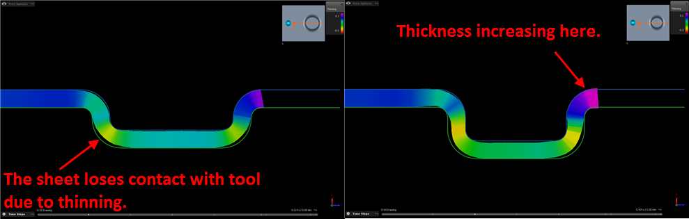
With recent releases of AutoForm, the ability to view THICKNESS of the actual sheet metal, including any increase/decrease in metal thickness, became possible. Although the 3D dimensional view illustrates a 3D color map of thickness distribution after the metal forming process, it’s more useful to see the actual sheet thickness in a cross section.
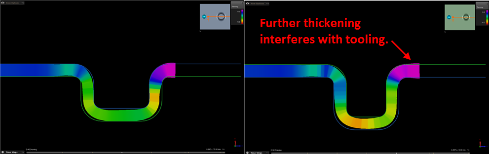
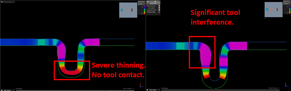
This allows the tooling engineer to clearly see where thickness increase may interfere with tooling OR where a reduction in sheet thickness may result in lost contact with the tooling surfaces.
Typically, a tooling engineer and their tool makers must manually allow for this by “spotting in” the tools during a physical tool tryout. The sheet metal blank may be “blued” to allow a clear indication of where the tool is hitting “hard”. This can subsequently relieved by a toolmaker, to ensure metal can flow unrestricted or as desired between the upper and lower tooling. This becomes most critical in a draw process.
AutoForm sheet metal forming simulation software is hinting (but certainly not confirmed) that this could become an automated process sometime in the future. Imagine if you could export all your 3D tooling surfaces from the simulation with correct relief/clearances in all the right places, with no further adjustments required during tryouts in the press.
That’s what the future holds.