Calculating Tensile Strength Accurately For Simulation Use
There are many sheet metal projects and parts that need to be stretched or deep drawn, so choosing the right material and manufacturing process is extremely important. Besides affecting the performance of your product, using simulations to find the ideal material and manufacturing process can also help you save time and money in the long run. Before that, however, we must accurately determine the material’s tensile strength and failure point using the uniaxial tensile test.
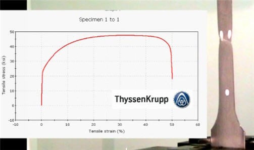
We have covered the uniaxial tensile test a few times in the past here. In particular, we have shown video of the process used at Thyssen Krupp Steel to test 12” x 12” samples in the 0-, 45-, and 90-degree directions. The basic test result looks like this:
Now what if we were to run a simulation of the uniaxial tensile test? Perhaps there is no practical purpose, but in this article, we set up and run a dog bone sample through AutoForm for the sake of interest and to demonstrate how we can simulate a tool that can clamp and pull a sheet in the horizontal direction.
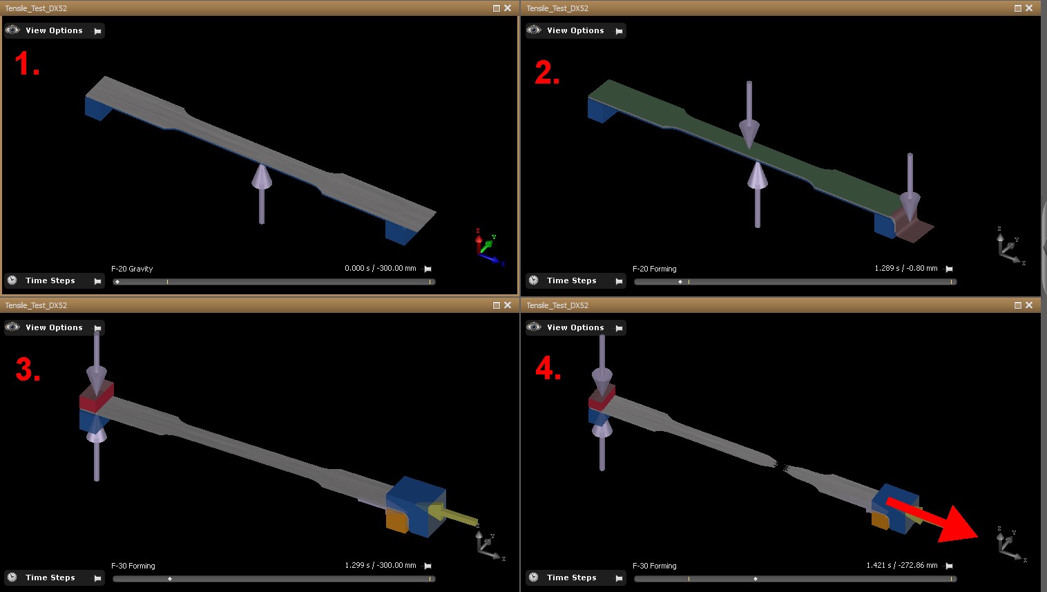
1. A dog bone cad model is imported into AutoForm R7 to be used as the sheet
2. Because we must grip and then pull the sheet (without it releasing) it was concluded a flange was needed to enable tooling to securely hold the sheet during the pulling action. Without the flange, the sheet would slip through the tooling, instead of straining and pulling the sheet, as per the uniaxial tensile test.
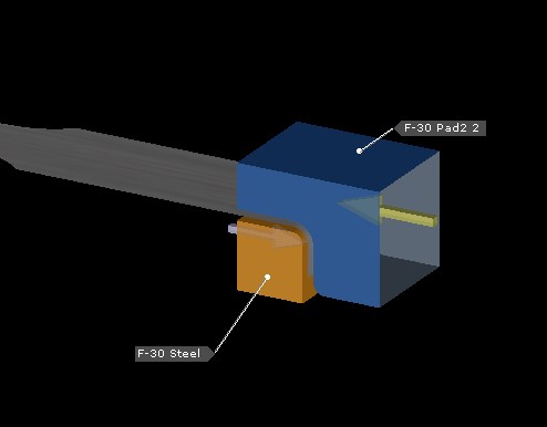
3. Solid tools were modeled and imported to AutoForm R7, to locate and clamp the dog bone sample. A rigid CAM STEEL (F-30) was used as the main driver of the pulling action on a horizontal CAM vector, with 300mm CAM stroke.
4. To clamp and hold the end of the sample, an upper PAD (F-30 Pad2) was used, also on the same horizontal CAM vector. The tool type was “spring controlled”, allowing the flange shape to lock the sample in place and prevent it pulling through the tooling block. A “cushion stroke” of 300mm was assigned, to allow it to travel with the CAM STEEL.
View the full video of the simulation here:
Want to Learn More?
Interested in learning more about what is possible with advanced forming simulation software? Visit our case studies page to see what we’ve done for previous clients, or contact us today for more information.