The 5 Most Important Parameters to Consider During Metal Forming Simulations
Contents
Metal forming simulation technology is still a very new tool to many. Because of this, it may be hard to take the plunge when hiring these services or looking to buy simulation software. Some may be worried that simulations are not 100% accurate, leaving them with tooling projects that have problems. However, simulation detects any potential problems such as wrinkles or splits in the material, as well as the end strength and material thinning results. Simulation technology can also calculate and compensate for springback, as well as accurately calculate complex trim/blank developments through multiple forming operations.
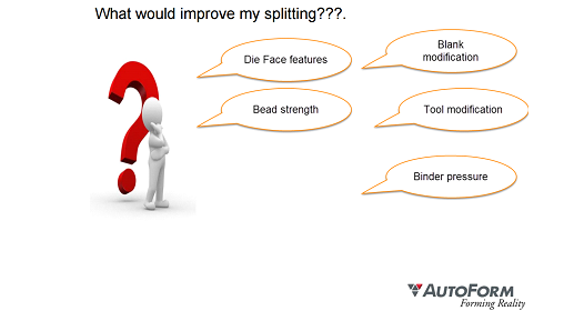
Important Parameters During Metal Forming Simulations
Incremental forming simulation technology, such as AutoForm, always considers the complete 3D geometry of each forming stage and simulates every increment of the forming process. The mechanical properties of the sheet metal material being simulated are of extreme importance and are used in the simulation directly. The stress and stress are calculated at a finite number of points on the sheet using the Finite Element Method (FEA or FEM).
StampingSimulation uses AutoForm incremental sheet metal forming simulation software to perform advanced simulation analysis for all sheet metal forming processes, and considers the 5 most important parameters to be as follows:
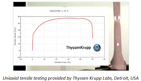
⦁ Mechanical properties of the sheet: No simulation (general to all FEA simulations) is accurate without confirmation of the mechanical properties of the sheet metal being formed. StampingSimulation provides a fast and inexpensive testing service to correctly test and capture stress-strain data for any sheet metal material, to be used in simulation. Without this test, simulation has no basis for accuracy, and therefore cannot be considered reliable.
⦁ Tooling geometry used in simulation must match tooling manufactured, exactly: A 3D tool design simulated and validated in simulation, must be continued (without change) to the tool room floor. Any changes to the tooling process steps or shapes must be re-validated in simulation to avoid an unexpected outcome in reality. For this reason, StampingSimulation provides “Final Validation” for every job. No tooling component should be machined until their final revision level is validated in simulation. A developed blank shape (or trim profile) must also match the one used in simulation, to expect the same result in reality.
Simulation matches reality, for better or worse!
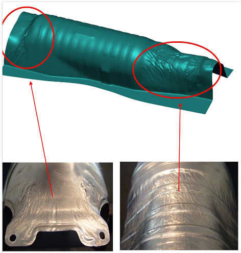
⦁ Tooling forces calculated in simulation, must be available in the chosen press equipment: All tooling forces, including total ram force, binder forces, pad forces, draw bead hold down forces are accurately calculated in simulation. If tooling in the real world is placed in a press with less than required tonnage (or if peak forces occur at the de-rated tonnage cycle of the press), then results found in simulation cannot be achieved in reality. Furthermore, binder forces that use gas cylinders or other spring systems, must closely match those found in simulation, in order to achieve the same result in reality.
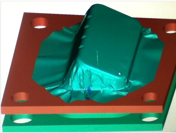
Insufficient binder tonnage.
⦁ Tooling Clearances: Deep draws with vertical walls (ie: cups) require special attention to clearances. Whilst many simple tools can be machined size for size with little or no clearance, deep draws (especially with vertical walls) cannot. Simulation uses “perfect” tooling and will show exactly where thickening will occur. However, tooling clearances must be added by the toolmaker to correctly allow material to flow (avoid locking up) during a complex deep draw or similar parts. For very high strength materials, such as stainless steel, clearances may need to be as much as 30% of material thickness.
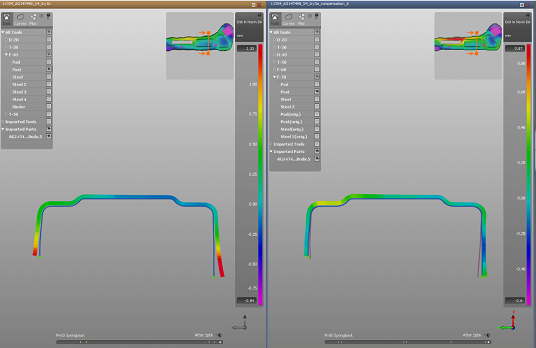
Section Views in AutoForm show thickening/thinning to allow toolmakers to determine where and how much clearance to add to tooling.
⦁ Lubrication of tooling surfaces:. Simulation “factors in” the exact friction values of all tooling faces. A simulation that uses artificially low friction values may make a part successfully in the virtual world but may never be replicated in reality. StampingSimulation uses reasonable friction values for all tooling, and only applies special friction values (or lubrication) if the same can be achieved in reality. In some cases high friction values (ie: rough finish) may be required to achieve a successful forming outcome.
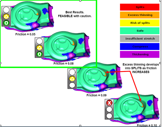
Friction values can make or break a part. In reality, low friction values can only be achieved with special tool coatings and special blank treatment.
Learn More
StampingSimulation uses AutoForm-DieDesignerplus tools to efficiently and effectively create a successful forming process, starting with nothing more than the final product model.
To learn more about how our processes can assist you, contact us today.