Simulating the Stamping Process
The methodology of simulating a sheet metal stamping process has become a formality, thanks to continuous advancements in simulation software, and more specifically AutoForm simulation technology.

Sheet metal stamping simulation is a nonlinear problem in that the material behavior does not follow a simple linear model, as would be the case for a static load problem. A static load problem only considers the elastic portion of the material’s behavior such that the load never induces permanent (or plastic) deformation in the structure. These problems are relatively simple to solve, and there are many robust and efficient simulation software packages that cater for this type of problem.
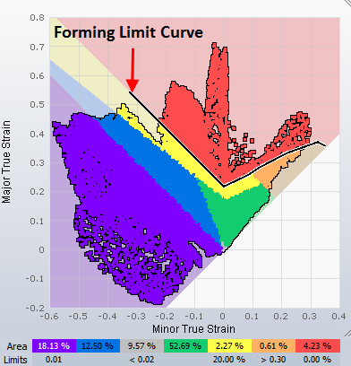
However, sheet metal stamping simulation focuses almost entirely on the fact that the material being formed must be pushed past its elastic limit and into the plastic region where permanent deformation will occur. To make the problem more difficult, the permanent deformation must be limited to the maximum the material will allow, otherwise splitting (failure) will occur. This is known as the forming limit of the material.
Because the stress-strain relationship of the material (usually sheet metal) is nonlinear, the calculations become complicated and heavily time dependent. Collecting the correct material properties is also a more complex task, since the mechanical properties of the material must be recorded during plastic deformation, up to the point of failure.
To set up, calculate and evaluate a nonlinear simulation problem is a complex task and without software optimized for this task, it becomes incredibly daunting and sometimes impossible. Whilst a few software companies offer sheet metal forming simulation solutions (almost always based on the LS-DYNA solver), only AutoForm is truly proven to be the optimized solution for speed, accuracy, ease of use and solver robustness.
The process of simulating in AutoForm is much less like a PhD thesis, and more like an optimized workflow that might be similar to using 3D CAD software, with superior functionality. Tasks such as creating the FEA mesh (critical to simulating imported three dimensional tooling shapes) become automated, and reliable, to the point where the meshing process is almost entirely in the subconsciousness of the user……manual mesh repair or adjustments are never required in AutoForm.
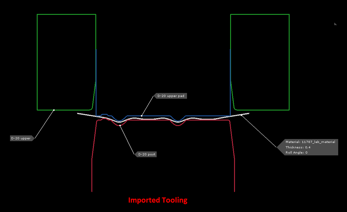
Tooling geometry is imported and assigned labels such as punch, binder and die. Travel curves for the solid tools are generated automatically, as are tooling offsets (if required). Furthermore, complex pads/lifters/ejectors/strippers can be included with very little input required from the user. Complex tooling setups and the resulting tooling travel curves are effortlessly added to the simulation when using AutoForm.
Tools and operations can be imported to AutoForm very much the way they are setup in reality, including upper/lower opposing pads that work against each other. It’s also entirely straightforward to setup complex cam timings and hemming operations, be they roller hem or traditional hemming.
Assessment of results is superior in AutoForm with the concept of “post processing” 100% integrated in the main interface. Perhaps the most impressive feature is the ability to see actual sheet thickness changes in the cross sectional views, a function that I have not seen repeated in any other software.
At Stamping Simulation, our team is familiar with multiple types of forming simulation software. We’d love to be your stamping simulation solution! Contact our team to get a free quote or view our case studies to see how we’ve been able to partner with others in creating complex manufacturing projects.