Product Development
- Early formability checks
- Rapid evaluation of multiple designs
- Blank size estimation
Planning & Bidding
- Process planning
- Tonnage calculations
- Material cost studies
Tooling
- 3D process design and simulation
- Precise virtual tryout of 3D tooling
- Accurate blank and trim development
- Integrated springback compensation
- Comprehensive results: formability, thinning, springback, surface quality
Production
- "What if" scenario assessments
- Process improvement studies
- Material change studies
- Cost reduction studies
- Root cause analysis of existing production problems
 The Challenge:
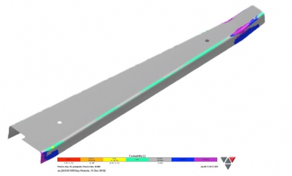 Connecticut Corsair is a volunteer organization dedicated to the promotion of education and local businesses in the State of Connecticut. They are also leading an aircraft restoration project aimed at restoring to flight the official State Aircraft of Connecticut — the Chance-Vought F4U Corsair.
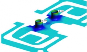
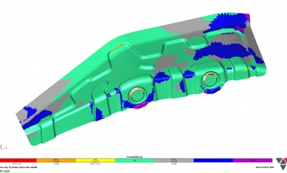 Die Engineering Pty Ltd, a regular StampingSimulation customer, needed to be sure that a part of a complex project could be formed successfully. Earlier prototype parts had been made with unacceptable wrinkles and it was, therefore, the job of our simulation team to determine how to make this part in a way that prevented any wrinkling.