5 Ways AutoForm Makes Tool Design More Efficient for Sheet Metal Parts
Contents
When 2D CAD systems were introduced in the late 1980s, drawing boards everywhere became obsolete. In the 1990s, 2D drawing systems became 3D and those who utilized 3D solid modelling correctly could generate 2D views/details automatically.
Today, designers of sheet metal tooling need never draw in 2D again since all 2D views/details are generated from the 3D model by advanced CAD software systems. It would be considered very inefficient to design a tooling project in 2D.
3D solids become 2D sections or drawings at the click of a button.
5 Ways AutoForm Maximizes Tool Design
A similar – but less accepted – shift has already occurred in the world of sheet metal forming simulation. Advanced AutoForm software features allow engineers to design sheet metal tooling processes in 3D without an advanced CAD system. In fact, 3D CAD modelling of tooling is the last step of an efficient sheet metal forming simulation.
When sheet metal forming simulation was first introduced, it was thought that the entire tool had to be designed in 3D CAD as the first step, before a simulation could take place. Furthermore, for progressive type tooling the first step was always to create a full 3D strip model, complete with blank, carrier and stretch web details before any confirmation of a successful forming process!
Here’s how AutoForm turns this inefficient thought process on its head, and puts 3D design into the incremental simulation process:
- Only the final 3D product geometry is imported into AutoForm. All tooling shapes/steps are designed using advanced AutoForm-DieDesigner software module, working backwards from final form to first draw and every step in between.
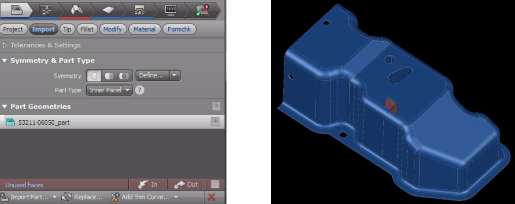
- AutoForm-DieDesigner functions are parametric and hold logical relationships with the model but without the restrictions often found in CAD systems. A whole new approach to 3D modeling is created inside AutoForm without touching CAD, and efficiency is improved many times compared to importing tooling surfaces created in CAD. Needless to say, the geometry created inside AutoForm-DieDesigner is ready for simulation instantly and linked directly to the simulation setup.
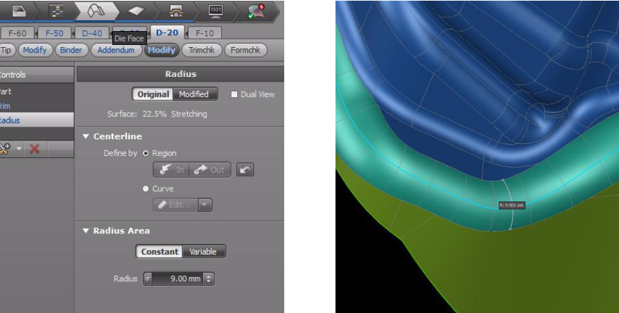
A radius in AutoForm can be updated much faster than in CAD.
- AutoForm-Trimline Optimization determines the correct blank shape and size using iterative simulations. Stretch webs, blank size, pitch and traditional details are ignored initially for investigative simulations. These details are not finalized until a working simulated forming process is completed. Traditional designers manually calculate (or guess!) the correct blank shape/stretch web/pitch only to find out in simulation their idea was not successful, and must then use large amounts of time re-designing in CAD. AutoForm does this in simulation, without any CAD software.
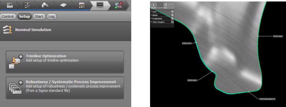
Trim targets are set during TrimLine Optimization
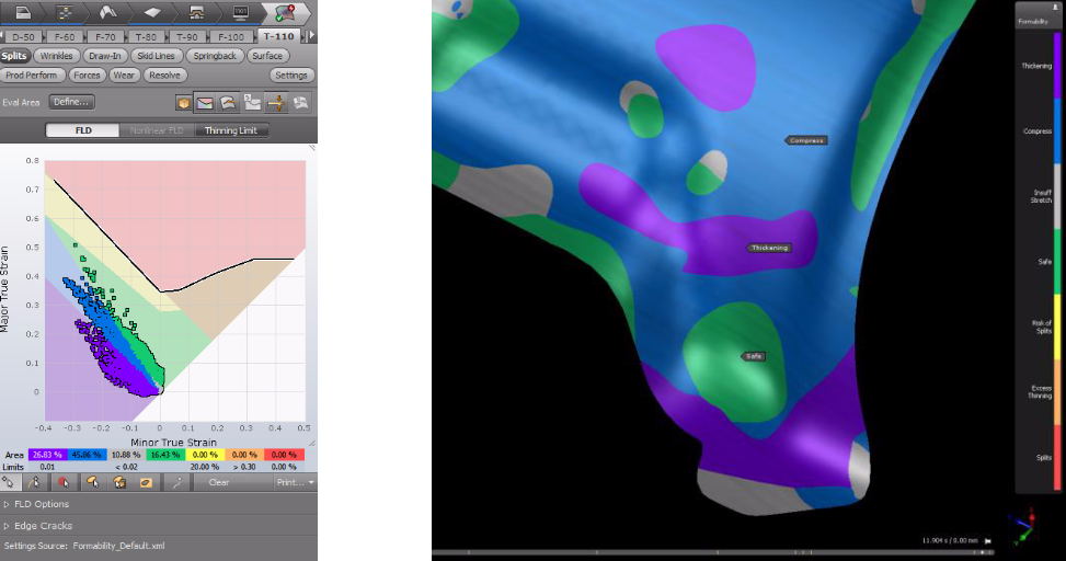
- AutoForm allows infinite definition and evaluation of alternative tooling geometry by simulating over and over again, adjusting geometry many times based on simulation results. The “trial and error” is not only done in simulation, it’s done without an external CAD system. Designs are “safe” only when AutoForm shows no problem areas and is confirmed by a human.
- The LAST step in an efficient AutoForm tool design is to EXPORT the geometry from the simulation. AutoForm R7creates IGS surfaces on the fly based on the FEA mesh used in the incremental simulation. Draws, preforms, developed blanks, stretch webs, carriers, etc, can all be exported and then imported to any CAD system to create the final tooling shapes that have already been proven in simulation.
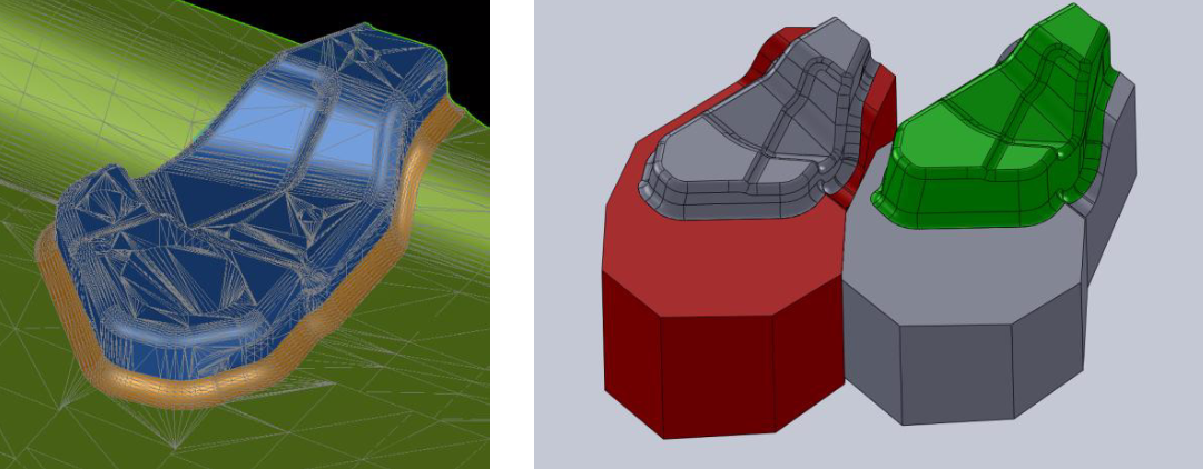
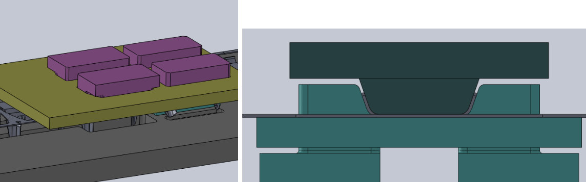
Geometry created in AutoForm-DieDesigner is exported and turned into solids in CAD as the final step.
Improved Simulation Results
We call the above 5 steps “SimulateComplete”. What used to take days and weeks of switching between CAD and simulation now takes just hours. In a recent benchmark study, we found a pure CAD based approached to simulation took a full 2 weeks to obtain a less than optimized result. When StampingSimulation approached the same part using “SimulateComplete”, a better result was achieved in just 8 hours.
To learn more about how our process works, click here.